
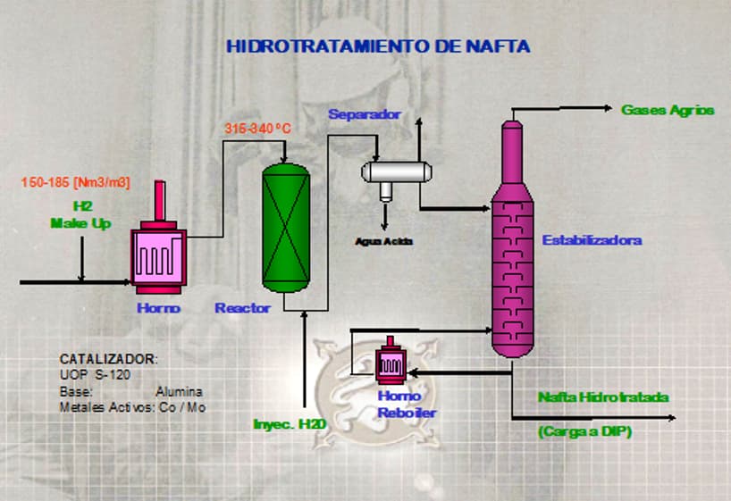
Hydrotreating Unit (Formerly ExHydrobón) (UOP S-120)
OBJECTIVE:
The main objective of the hydrotreating process is to condition the feed for the Isomerization Unit.
The removal of metals, as well as sulfur, oxygen, and nitrogen, is necessary because these elements act as poisons to the catalysts.
DESCRIPTION OF EQUIPMENT COMPOSING THE UNIT:
Makeup Gas Compressor [P-C2 A/B]: Reciprocating compressor, 75 kW, nominal flow of 3100 Nm³/hr.
Makeup Gas Spilback Cooler [P-E15]: Double-pipe heat exchanger, 3 m² exchange area, water-cooled.
Makeup Gas Knockout Drum [P-V5]: 1200 mm in diameter, 3000 mm tangent-to-tangent length, equipped with demister.
Feed Surge Drum [P-V23]: 1700 mm diameter, 5100 mm tangent-to-tangent length, equipped with water removal boot.
Feed Surge Drum Water Pump [P-P14]: Reciprocating pump, 1200 liters/hour capacity.
Hydrotreating Charge Pumps [P-P1 A/B]: Centrifugal pump, nominal capacity 24.6 m³/hr, 25 kg/cm² pressure differential. Power: 75 kW.
Hydrotreating Combined Feed Exchangers [P-E1 A/B/C]: Shell-and-tube heat exchangers, each with 9 m² heat transfer surface.
Charge Heater [P-H1]: Vertical cylindrical charge heater, 58.6 m² heat transfer surface, equipped with three dual-fuel burners (Fuel Gas/Fuel Oil).
Hydrotreating Reactor [P-V16]: Fixed-bed hydrotreating reactor, 1070 mm internal diameter, 3500 mm tangent-to-tangent length. Design temperature: 385°C. Design pressure: 33 kg/cm².
Hydrotreating Reactor Products Condenser [P-E2]: Forced-draft air cooler, 78.8 m² heat transfer surface. Equipped with three 25 HP fans, 1800 rpm, variable pitch.
Hydrotreating Separator [P-V1]: Three-phase separator, 1370 mm internal diameter, 4570 mm tangent-to-tangent length. Equipped with demister and boot for acidic water drainage. Design pressure: 27.5 kg/cm².
Hydrotreating Stripper Feed Exchangers [P-E3 A/B]: Shell-and-tube heat exchangers, 18.3 m² heat transfer surface.
Hydrotreating Stripper [P-V2]: Sour gas stripping column, equipped with 20 equilibrium stages. Tangent-to-tangent height: 16678 mm. Diameters: 1220 mm (stripping section) and 760 mm (rectification section). Design pressure: 14 kg/cm².
Stripper Reboiler Pumps [P-P4 A/B]: Centrifugal circulation pumps, 65.4 m³/hr capacity. Power: 30 kW.
Stripper Reboiler Heater [P-H2]: Vertical cylindrical heater, 5 m² heat transfer surface, with three dual-fuel burners (Fuel Gas/Fuel Oil).
Stripper Condenser [P-E4]: Forced-draft air cooler, 7 m² heat transfer surface. Equipped with three 18.7 kW fans, 1800 rpm, variable pitch.
Stripper Receiver [P-V3]: Three-phase separator, 914 mm internal diameter, 3048 mm tangent-to-tangent length. Equipped with boot for acidic water drainage. Design pressure: 14.1 kg/cm².
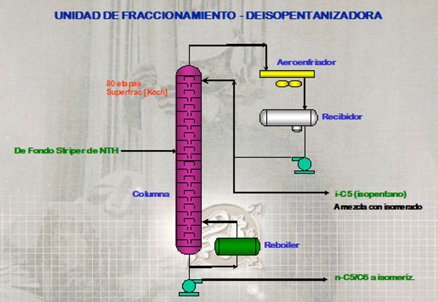
Fractionation Unit (Deisopentanizer Column)
OBJECTIVE:
The main objective of this processing unit is to separate the high-octane fraction (isopentane) from a cut suitable for isomerization (linear-chain C5/C6).
The unit consists primarily of an 80-stage fractionation column with its corresponding peripherals and auxiliaries:
Overhead condenser (air-cooled)
Overhead receiver with reflux/distillate pumps
Thermosiphon reboiler heated with low-pressure steam
Bottom pumps
DESCRIPTION OF EQUIPMENT COMPOSING THE UNIT:
Deisopentanizer Column [P-V21]: Fractionation column with 80 stages, equipped with next-generation Koch-Superfrac® trays. Tangent-to-tangent height: 54100 mm. Diameter: 1700 mm.
Deisopentanizer Reboiler [P-E17]: Thermosiphon reboiler heated with low-pressure steam. Shell-and-tube type.
Deisopentanizer Bottom Pumps [P-P12 A/B]: Centrifugal pumps designed for low NPSH. Capacity: 21.6 m³/hr. Power: 24 kW.
Deisopentanizer Overhead Condenser [P-E18]: Forced-draft air condenser, 257 m² heat transfer surface. Equipped with four variable-speed fans. Total power: 102.4 kW.
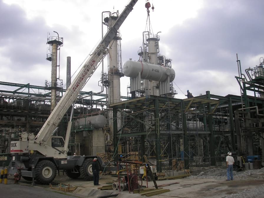
Deisopentanizer Receiver [P-V22]: 1600 mm diameter, 5400 mm tangent-to-tangent length. Design pressure: 4 kg/cm².
Deisopentanizer Overhead Pumps [P-P13 A/B]: Centrifugal pumps, nominal capacity 68.9 m³/hr, 4.5 kg/cm² pressure differential. Design power: 23 kW.
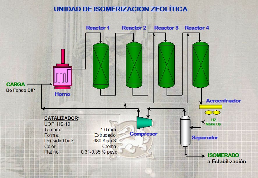
ISOMERIZATION UNIT
CONCEPT:
It is a molecular rearrangement process of low-octane linear paraffins (pentane and hexane), resulting in a higher-octane naphtha (isomerate) by forming the corresponding branched-chain isomers.
ISOMERIZATION UNIT
DESCRIPTION OF EQUIPMENT COMPOSING THE UNIT:
Isomerization Charge Heater [P-H3]: Vertical cylindrical charge heater with a 90 m² heat exchange surface, equipped with three dual-fuel burners (Fuel Gas / Fuel Oil).
Isomerization Reactor No. 1 [P-V17]: Fixed-bed isomerization reactor, 1372 mm internal diameter, 1677 mm tangent-to-tangent length. Design temperature: 543°C. Design pressure: 23 kg/cm².
Isomerization Reactor No. 2 [P-V18]: Fixed-bed isomerization reactor, 1524 mm internal diameter, 1500 mm tangent-to-tangent length. Design temperature: 543°C. Design pressure: 23 kg/cm².
Isomerization Reactor No. 3 [P-V19]: Fixed-bed isomerization reactor, 1676 mm internal diameter, 2133 mm tangent-to-tangent length. Design temperature: 543°C. Design pressure: 23 kg/cm².
Isomerization Reactor No. 4 [P-V20]: Fixed-bed isomerization reactor, 1829 mm internal diameter, 2896 mm tangent-to-tangent length. Design temperature: 543°C. Design pressure: 23 kg/cm².
Isomerization Combined Feed Exchanger [P-E5]: Shell-and-tube heat exchanger with a 309 m² exchange surface. Maximum design temperature: 543°C. Maximum design pressure: 21.5 kg/cm².
Isomerization Reactor Products Condenser [P-E6]: Forced-draft air cooler condenser, 7 m² exchange surface. Equipped with three 21.4 kW, 1800 rpm fans.
Isomerization Low Pressure Separator [P-V4]: Vertical two-phase separator with demister, 1220 mm internal diameter, 3660 mm tangent-to-tangent length. Design pressure: 18.3 kg/cm².
Low Pressure Separator Pumps [P-P6 A/B]: Centrifugal pumps, 22 kW power, 20.7 m³/hr pumping capacity, and 8 kg/cm² pressure differential.
Isomerization Recycle Gas Compressor [P-C1]: Centrifugal compressor, 11,545 rpm, with a circulation capacity of 13,430 Nm³/hr. Power: 257 kW.
STABILIZATION UNIT
OBJECTIVE:
The main purpose of this unit is to stabilize the product emerging from the isomerization reactors by fractionating the feed stream into light ends, primarily formed during the cracking processes that take place inside the reactors, resulting in C4 and lighter streams.
Based on a pre-existing unit at the plant, it will produce a separation between stabilized isomerate, gases, and an LPG fraction.
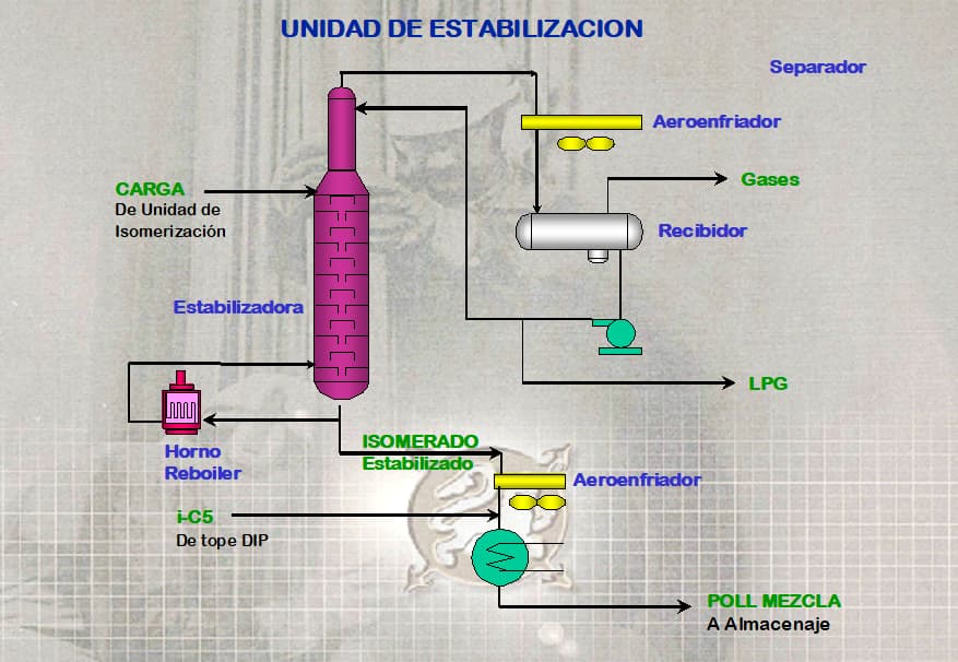
STABILIZATION UNIT
DESCRIPTION OF EQUIPMENT COMPOSING THE UNIT:
Isomerization Stabilizer Column [P-V6]: Stabilizer column for isomerized naphtha, equipped with 30 equilibrium stages, 21,960 mm tangent-to-tangent height, and diameters of 1220 mm and 762 mm for the stripping and rectifying sections, respectively. Design pressure: 20.4 kg/cm².
Stabilizer Reboiler Pumps [P-P8 A/B]: Centrifugal circulation pumps with a capacity of 78.6 m³/hr. Power: 22 kW.
Stabilizer Reboiler Heater [P-H7]: Vertical cylindrical charge heater with a 53 m² heat exchange surface, equipped with three dual-fuel burners (Fuel Gas / Fuel Oil).
Stabilizer Condenser [P-E9]: Forced-draft air cooler condenser with a 58.4 m² exchange surface. Equipped with 9.4 kW, 1800 rpm variable-pitch fans.
Stabilizer Receiver [P-V7]: Two-phase separator with an internal diameter of 1067 mm and 3660 mm tangent-to-tangent length. Design pressure: 20.4 kg/cm².
Stabilizer Overhead Pumps [P-P7 A/B]: Centrifugal circulation pumps with a capacity of 8.3 m³/hr. Power: 6 kW.
Stabilizer Reboiler Pumps [P-P8 A/B]: Centrifugal circulation pumps with a capacity of 78.6 m³/hr. Power: 22 kW.
Isomerate Trim Cooler [P-E16]: Multi-tube heat exchanger with a 17.4 m² exchange surface, cooled by cooling water.
Isomerate Cooler [P-E10]: Forced-draft air cooler with a 928 m² heat exchange surface. Equipped with 7 kW, 1800 rpm variable-pitch fans.
Isomerate Stabilizer Feed Exchangers [P-E8 A/B]: Shell-and-tube heat exchangers, each with a 10.9 m² exchange surface and a maximum design pressure of 22.2 kg/cm².
STORAGE UNIT
DESCRIPTION:
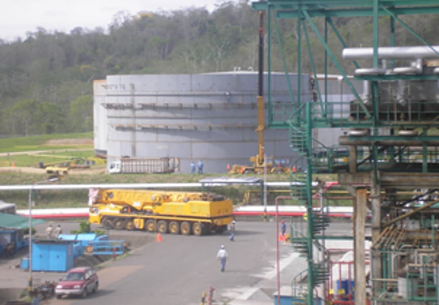
This unit consists of a pressurized API 620 tank equipped with state-of-the-art instrumentation, complying with the most demanding technical standards for this type of equipment. Due to the process specifications and technical requirements, this installation becomes the first of its kind in Ecuador.
It is associated with a pumping station with a capacity of 350 m³/hr, allowing the stored product to be sent to the Refinery’s Blending Unit.
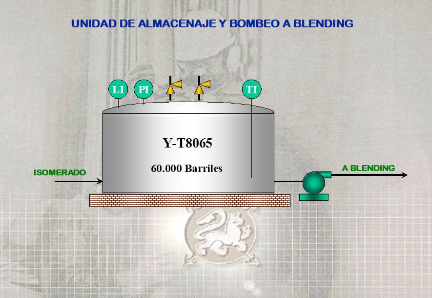
DESCRIPTION OF EQUIPMENT COMPOSING THE UNIT:
60,000 Bbl Pressurized Tank built under API 620 Standard, with a domed roof.
Pumping Station with a capacity of 350 m³/hr.
Control Instrumentation and Transfer Lines.
Tank Fire Protection System.
Three Motorized Valves: 8″, 6″, and 4″.
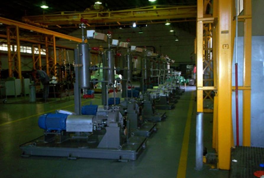
Design, engineering, construction, supply, and installation of 12 single-stage horizontal centrifugal pumps for industrial use, in compliance with API 610 10A standard, S10 metallurgy, with double mechanical seal and “M” coupling.
DESCRIPTION OF EQUIPMENT COMPOSING THE UNIT:
TSHO 2×4 13 Pumps, Series 06AB0637/38
1.5 HPXM 12 Pumps, Series 06AB0639/40
2 HPX 13 A Pumps, Series 06AB0641/42
1.5 HPXM 12 A Pumps, Series 06AB0644/44
1.5 HPXM 12 A Pumps, Series 06AB0646/46
2 HP 13 A Pumps, Series 06AB0647/48
DESCRIPTION:
Supply of materials, fabrication, and installation of the metallic structure, access stairs, floor plates, walkways, handrails, grating, primer coating, and other components of the metallic structure that supports equipment P-V22.
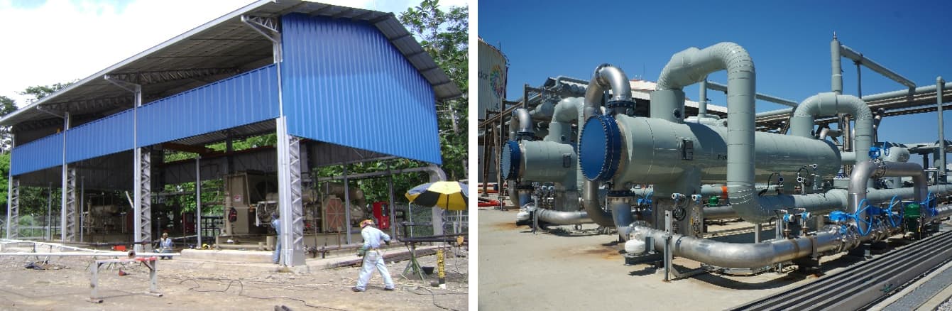
The contract for the “Supply, Installation, Testing, and Commissioning of Gas Compression Systems at the Norte 1, Norte 2, Central, and South Stations of PETROINDUSTRIAL (EP PETROECUADOR) in the Sacha Field” was a landmark project with significant national benefits, including the following:
It was essential to utilize the associated gas from the Sacha field, as 7 million cubic feet per day were previously being flared and wasted.
It contributed to reducing the national LPG production deficit by increasing output by approximately 26,000 tons per year, which, at average international prices, translated into savings of USD 19.14 million by avoiding higher-priced gas imports.
It increased the production of natural gasoline by 30 cubic meters per day, regularly used for blending extra gasoline, generating an additional annual saving of approximately USD 6.49 million.
It increased by 30% the feed of compressed gas and liquids to the Gas Plant in Shushufindi.
It delivered around 4.0 MMSCFD of dry residual gas to Petroproducción for use as high-efficiency fuel, reducing diesel consumption.

Derco Bass Group S.A., in consortium with the electric power distribution company in Mendoza, Argentina, DISTROCUYO S.A., managed over a period of approximately 10 years, 8 contracts for the Measurement, Maintenance, and Monitoring of Special Clients for Empresa Eléctrica Quito (EEQ), earning first place from ECUACIER for the design of the Remote Metering System currently operated by the service company.